The Tool
One feature that I like to use in ETABs is the section cut tool, but it is quite cumbersome to utilize in practice:

Notice how you have to enter (4) valid points to define a section cut... a time consuming process. I love to use this tool to analyze my diaphragm forces, but you are only left with snapshots of your total diaphragm moment and shear. Defining lots of these section cuts along the length of a diaphragm is tedious.
This tool allows structural engineers to select their diaphragm in ETABs, define the slicing direction and define the number of sections to generate, plotting shear and moment at each section cut. It yields awesome plots like the following that you can use to determine diaphragm shear force and moments. The example shown below is that of a (3) sided diaphragm, 40ft long, with a 1kip/ft load applied to edge of the diaphragm.


Diaphragm Shear - Total Shear at shear wall is 40 kips
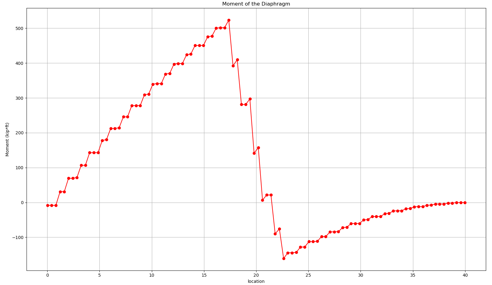
Diaphragm Moment
The shear graph above makes sense 1 kip/ft * 40ft = 40 kips to be resisted by singular shear wall in the line of the applied force; while on the other hand, the moment in the diaphragm is a little counter intuitive. This graph will make me revisit my other three sided diaphragm post at a later date.
The Goods
You can find the code to make this happen on my github as well as the sample ETABs model utilized to generate all of the plots. The code is written in python and utilizes the ETABs API to do the leg work.
A big thanks to CSI for making this possible in ETABs v19 and above. The new API of ETABs allows engineers to programmatically access any of the available tables in the interactive database. This bit of code makes the section cuts for the diaphragm:
def make_quad_etabs(name_sect,point):
    name = str(name_sect)
    final = []
    for i in range(4):
        if i == 0:
            test = [name, 'Quads', 'All', 'Analysis', 'Default', '', '', '', '0','0','0','','Top or Right or Positive3','1', '1', '1', str(point[0][0]), str(point[0][1]), str(point[0][2]), '1']
            final.append(test)
        elif i == 1:
            test = [name, '', '','', '', '', '', '', '','','','','','', '1', '2', str(point[1][0]), str(point[1][1]), str(point[1][2]), '']
            final.append(test)
        elif i == 2:
            test = [name, '', '','', '', '', '', '', '','','','','','', '1', '3', str(point[2][0]), str(point[2][1]), str(point[2][2]), '']
            final.append(test)
        elif i == 3:
            test = [name, '', '','', '', '', '', '', '','','','','','', '1', '4', str(point[3][0]), str(point[3][1]), str(point[3][2]), '']
            final.append(test)
    return final

etabs_data_sect = []
for i,(etabs_quad,sec_name) in enumerate(zip(global_quad,name)):
    etabs_data_sect.append(make_quad_etabs(sec_name, etabs_quad))

flat_etabs_data = []
for point in etabs_data_sect:
    temp = []
    for data in point:
        for sing_data in data:
            temp.append(sing_data)
    flat_etabs_data.append(temp)
mega_data = []
for point in flat_etabs_data:
    for ind_pnt in point:
        mega_data.append(ind_pnt)

TableKey = 'Section Cut Definitions'
TableVersion = 1
FieldsKeysIncluded = ['Name', 'Defined By', 'Group','Result Type', 'Result Location', 'Location X', 'Location Y', 'Location Z', 'Rotation About Z','Rotation About Y', 'Rotation About X', 'Axis Angle', 'Element Side', 'Number of Quads', 'Quad Number', 'Point Number', 'Quad X', 'Quad Y', 'Quad Z', 'GUID']
NumberRecords = len(flat_etabs_data)


y = SapModel.DatabaseTables.SetTableForEditingArray(TableKey, TableVersion, FieldsKeysIncluded, NumberRecords,mega_data)

FillImport = True
z= SapModel.DatabaseTables.ApplyEditedTables(FillImport)
model_has_run = SapModel.Analyze.RunAnalysis()
To use the code, select your floor and change any of the input that I have noted with the #UI note in the python code.
Typical user input includes:
- Selecting the diaphragm you want to slice up, this is done in the ETABs model
- Select the vector direction you want to your diaphragm to be sliced up, (1,1,0) for example is going up and to the right at a 45 degree angle, in the example below, (1,0,0) tells the program to create vertical slices along the length of the diaphragm, moving from left to right.
- Define the number of slices you want to make
- # UI Number of slices to make along the diahragm
n_cuts = 100
- Set the hieght, in feet, that your diaphragm exists at in ETABs
- Set the starting location of you diaphragm
- Hit the run button on your favorite IDE
After hitting run, the program will generate the number of section cuts you told it to create and matplotlib is utilized to plot the results.
In my example code, I had the program generate 100 cuts, the 100th cut corresponds to the section cut 0099 noted below.

A nice plot is generated at the beginning as well so you can see how you are slicing your diaphragm to make sure you made your user input correctly. The red dots below correspond to where your diaphragm exists, while the blue lines corresponds to your section cuts.

Overall the tool works well and I look forward to using it on more complicated diaphragms. Test it out and let me know what you think!
UPDATE: A much more stable version of the slicer is shown here, written in C#.