Diaphragm Analysis - My Journey
Most engineers will find a certain area of structural engineering that really excite them and areas that they absolutely despise, and for the longest time, I absolutely despised diaphragm design. Diaphragm design is complicated and confusing, my project managers loved to throw around the buzz phrases they had learned throughout their time in the industry:
- Did you consider that reentrant corner?
- Should we use full depth collectors?
- How are you analyzing the hole in your diaphragm?
These were all very valid questions, but when I asked them how they handle this, I was often left with responses that left me longing to dig deeper. Stuff like, "this hole is tiny, we don't need to consider it", "full depth collectors aren't needed, our forces are small"... etc. I wanted to know more.
This all changed when I discovered the book by Terry Malone, The Analysis of Irregular Shaped Structures Diaphragms and Shear Walls, he seemed to layout a logical, albeit math intensive, way to consider everything and anything one may encounter in diaphragm analysis.
The Humble 3 Sided Diaphragm
I present to you the humble 3 sided diaphragm in the image below:

Many structural engineers would like to analyze this like a cantilevered beam, but this cantilevered beam analogy falls short in a lot of regards.
Cantilevered beam analogy: Incorrect Chord Forces
Drawing the shear diagram for this diaphragm is pretty simple, the shear increases linearly within the diaphragm from right to left. It could yield a diagram like the following:

We know from structural analysis that moment is the area under the shear force diagram and it would yield the following moment diagragm:

A concerned engineer would know that this diagram creates some inherent problems when designing their chords. At the very left hand side of the diaphragm, there would be a very large axial chord force, e.g. from the image above ~950 kip*ft / (depth between your chords). Where does this axial force go? It can't just disappear into the abyss. Just recently I was reviewing a 3 sided diaphragm design by another engineer and they went on their way designing chords according to a diagram similar to that above. Do I think the diaphragm will now fail? Absolutely not, but I do think we could get a more accurate moment and corresponding chord force diagram.
The moment diagram (and corresponding chord axial force) needs to close to 0 at each end of the diaphragm in order for the diaphragm to be stable.
How does the moment diaphragm close to 0? One needs to consider the corresponding lateral resisting system (LRS) in the direction perpendicular to the applied loading; these LRS elements take an equal and opposite reaction (also fun fact, these reactions will always be equal and opposite, independent of stiffness of the elements) that stabilize the diaphragm due to the eccentric applied load relative to the resisting lateral force resisting system.
Considering these perpendicular lateral force resisting elements, we get a diagram similar to this:

Horray! The diagram closes to 0 on both ends, oddly similar to a WL^2/8 type appearance.
UPDATE 04/23/2023: I no longer agree with the WL^2/8 appearance, I think the moment diagram is more akin to this diagram.
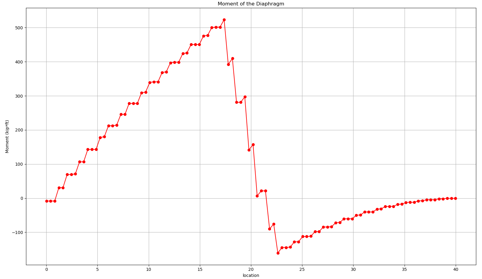
I also performed some computer modelling of this 3 Sided Diaphragm to see if the Terry Malone analysis methodology matched up with some finite element software. The results showed the exact same trends, the diaphragm moment and corresponding chord axial force in the diaphragm must go to 0 at the ends of the diaphragms.
Below is a plot of axial force in chord elements in the diaphragm, note how they close to 0 at the ends.

One of the other areas that the cantilevered beam analogy fails is the deflected shape of the diaphragm. For loading applied from page down to up, I would expect there to be a smile face up deflection deflected shape. ETABs and RAM deformed shapes of the diaphragm showed the exact opposite, a smilely face down deflection.


You can read about the counter intuitive deflection here: https://www.eng-tips.com/viewthread.cfm?qid=450755
The Takeaway
Diaphragm design cannot be reduced to a simple stick model.

The 2 dimensional nature of diaphragms and the corresponding in-plane and out-of-plane lateral resisting elements all play a role in stabilizing the diaphragm. A stick model can not account for the out-of-plane lateral elements.